Mechanical Seal vs Gland Packing - Complete Technical Comparison
In-depth comparison of mechanical seals vs gland packing for centrifugal pumps: API 682 requirements, flush plans, material selection, MTBF data, and selection criteria.
API 682API 610ISO 21049
Quick Reference
| Parameter | Mechanical Seal | Gland Packing |
|---|
| Typical Leakage | <0.5 ml/hr | 10-60 drops/min |
| Power Consumption | 0.1-0.5 kW | 0.5-3.0 kW |
| Service Life (MTBF) | 3-5 years | 3-12 months |
| Initial Cost | $500-$5,000+ | $50-$200 |
| Max Temperature | 400°C (special) | 260°C (graphite) |
| Max Pressure | 40 bar (single) | 20 bar |
| Shaft Speed Limit | 25 m/s | 15 m/s |
| Runout Tolerance | <0.05 mm | <0.25 mm |
| API Standard | API 682 | API 610 Annex |
How Each Sealing Method Works
Mechanical Seal Principle
A mechanical seal creates a seal through two precision-lapped faces—one rotating with the shaft, one stationary in the seal chamber. A thin fluid film (3-10 μm) lubricates the faces.
Key Components:
| Component | Function | Typical Materials |
|---|
| Rotating Face | Seals against stationary face, rotates with shaft | Silicon Carbide (SiC), Tungsten Carbide (TC) |
| Stationary Face | Fixed in gland, provides sealing surface | Carbon, Silicon Carbide (SiC) |
| Springs/Bellows | Provides axial load to maintain face contact | Hastelloy, 316 SS |
| Secondary Seals (O-rings) | Seals gaps between components | Viton, EPDM, Kalrez, FFKM |
| Drive Mechanism | Transmits torque from shaft to rotating face | Stainless Steel pins/lugs |
| Gland Plate | Houses stationary components, connects to pump | Cast Iron, 316 SS |
| Sleeve | Protects shaft, provides mounting surface | 316 SS, Hastelloy |
Face Flatness Requirement: 0.6-0.9 μm (3 light bands) - critical for preventing leakage
Mechanical Seal Assembly (Cartridge Type)
━━━━━━━━━━━━━━━━━━━━━━━━━━━━━━━━━━━━━━━━━━

        Gland Plate
           │
     ┌─────┴─────┐
     │           │
     │  ┌───────┐│ ← Stationary Face (carbon/SiC)
     │  │░░░░░░░││
     │  │       ││ ← Fluid Film (3-10 μm)
     │  │▓▓▓▓▓▓▓││ ← Rotating Face (SiC/TC)
     │  │       ││
     │  │ ╔═══╗ ││ ← Springs or Bellows
═════│  │ ║   ║ ││══════ Shaft
     │  │ ╚═══╝ ││
     │  └───────┘│
     │           │
     └───────────┘
         │
    Seal Chamber

Key Components:
• Rotating face - Attached to shaft via set screws
• Stationary face - Fixed in gland plate
• O-rings - Secondary seals (dynamic & static)
• Springs/bellows - Maintain face contact under all conditions
Face Flatness Requirement: 2-3 light bands (0.6-0.9 μm) per API 682
Gland Packing Principle
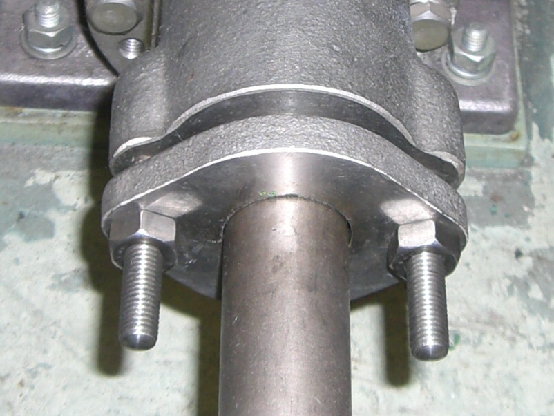
Pump with gland packing showing gland follower and stuffing box. Gland packing requires slight leakage (10-15 drops/min) for lubrication and cooling (Image credit: Miya.m - Wikimedia Commons, CC BY-SA 3.0)
Gland packing uses rings of braided material compressed around the shaft. Intentional leakage (10-15 drops/min) lubricates and cools the packing.
Gland Packing Assembly
━━━━━━━━━━━━━━━━━━━━━━━

        Gland Follower
           │     ← Adjustable compression (bolts)
     ┌─────┴─────┐
     │▒▒▒▒▒▒▒▒▒▒▒│ ← Packing Ring #1
     │▒▒▒▒▒▒▒▒▒▒▒│ ← Packing Ring #2
     │           │ ← Lantern Ring (flush distribution)
     │▒▒▒▒▒▒▒▒▒▒▒│ ← Packing Ring #3
     │▒▒▒▒▒▒▒▒▒▒▒│ ← Packing Ring #4
     │▒▒▒▒▒▒▒▒▒▒▒│ ← Packing Ring #5
═════│───────────│══════ Shaft Sleeve
     │           │
     └───────────┘
         │
    Stuffing Box

Key Components:
• Packing rings - 5-6 rings typical, staggered joints
• Lantern ring - Distributes flush water, positioned at flush connection
• Gland follower - Adjustable compression plate
• Shaft sleeve - Replaceable wear surface
Design Leakage: 10-15 drops/min minimum for lubrication and cooling
Mechanical Seal vs Packing: Detailed Comparison
| Seal Type | Leakage Rate | Visibility |
|---|
| Single mechanical seal | <0.5 ml/hr | Invisible (vapor) |
| Double mechanical seal | Zero to atmosphere | None |
| Tandem mechanical seal | <0.5 ml/hr to buffer | None visible |
| Gland packing (new) | 10-15 drops/min | Visible |
| Gland packing (worn) | 30-60+ drops/min | Continuous |
| Gland packing (failed) | Stream | Obvious |
Energy Consumption
Power Consumption Comparison (50 mm shaft, 3000 rpm)
━━━━━━━━━━━━━━━━━━━━━━━━━━━━━━━━━━━━━━━━━━━━━━━━━━━

Mechanical Seal (balanced):     ████ 0.3 kW

Gland Packing (adjusted):       ████████████████████████ 2.0 kW

Factor: 6× more power consumed by packing
Annual Energy Cost Example:
| Parameter | Mechanical Seal | Gland Packing |
|---|
| Friction power | 0.3 kW | 2.0 kW |
| Operating hours | 8,000 hrs/yr | 8,000 hrs/yr |
| Energy consumed | 2,400 kWh | 16,000 kWh |
| Cost @ $0.12/kWh | $288/yr | $1,920/yr |
| Annual savings | $1,632/yr | — |
Service Life (MTBF)
| Seal Type/Condition | Typical MTBF |
|---|
| API 682 Category 3 dual seal | 5-10 years |
| API 682 Category 2 seal | 3-5 years |
| API 682 Category 1 seal | 2-3 years |
| Standard industrial seal | 2-4 years |
| Quality graphite packing | 6-12 months |
| PTFE packing | 3-6 months |
| Standard packing | 2-4 months |
Shaft Tolerance Requirements
| Parameter | Mechanical Seal | Gland Packing |
|---|
| Radial runout | <0.05 mm TIR | <0.25 mm TIR |
| Axial endplay | ±0.5 mm | ±2-3 mm |
| Shaft deflection | <0.05 mm | <0.15 mm |
| Misalignment | Very sensitive | Tolerant |
| Surface finish | 0.4-0.8 μm Ra | 0.8-1.6 μm Ra |
API 682 Mechanical Seal Standard
Seal Categories
| Category | MTBF Target | Application | Features |
|---|
| Category 1 | 2 years | General industrial | Standard materials |
| Category 2 | 3 years | Moderate to severe | Upgraded materials |
| Category 3 | 5 years | Critical/hazardous | Premium materials, containment |
Seal Types
| Type | Description | Temperature | Application |
|---|
| Type A | Pusher seal with O-ring | -40 to 175°C | Standard services |
| Type B | Metal bellows | -40 to 260°C | High temperature, viscous |
| Type C | High-temperature bellows | -40 to 400°C | Extreme temperature |
Seal Arrangements
Arrangement 1: Single Seal
━━━━━━━━━━━━━━━━━━━━━━━━━
        Process
           │
    ┌──────┴──────┐
    │   ▓▓▓▓▓▓▓   │ ← Seal faces
════│═════════════│════ Shaft
    └─────────────┘
           │
        Atmosphere

Use: Non-hazardous fluids, API Plan 01/11/13/21/23/32


Arrangement 2: Dual Unpressurized (Tandem)
━━━━━━━━━━━━━━━━━━━━━━━━━━━━━━━━━━━━━━━━━━
        Process
           │
    ┌──────┴──────┐
    │   ▓▓▓▓▓▓▓   │ ← Inboard seal (primary)
    │             │
    │   Buffer    │ ← Buffer fluid (unpressurized)
    │             │
    │   ▓▓▓▓▓▓▓   │ ← Outboard seal (containment)
════│═════════════│════ Shaft
    └─────────────┘
           │
        Atmosphere

Use: Hazardous fluids, backup containment, API Plan 52


Arrangement 3: Dual Pressurized (Double)
━━━━━━━━━━━━━━━━━━━━━━━━━━━━━━━━━━━━━━━━
        Process
           │
    ┌──────┴──────┐
    │   ▓▓▓▓▓▓▓   │ ← Inboard seal
    │             │
    │   Barrier   │ ← Barrier fluid (pressurized)
    │   P+1 bar   │   P_barrier > P_process
    │             │
    │   ▓▓▓▓▓▓▓   │ ← Outboard seal
════│═════════════│════ Shaft
    └─────────────┘
           │
        Atmosphere

Use: Maximum safety, zero emission, API Plan 53A/53B/53C/54
Common API 682 Flush Plans
| Plan | Name | Description | Application |
|---|
| 01 | Internal circulation | Dead-ended seal chamber | Clean, cool fluids |
| 02 | Dead-ended | No circulation | Low vapor pressure |
| 11 | Recirculation + orifice | From discharge to seal | Cool, debris flush |
| 13 | Reverse flow | From seal to suction | Prevent settling |
| 21 | External cooler | Recirculation through cooler | High temperature |
| 23 | Pumping ring + cooler | Internal pumping through cooler | High temperature |
| 32 | External injection | Clean flush from external source | Dirty, crystallizing |
| 52 | Buffer fluid system | Unpressurized buffer reservoir | Arr. 2 tandem seal |
| 53A | Pressurized barrier (bladder) | Bladder accumulator | Arr. 3 double seal |
| 53B | Pressurized barrier (piston) | Piston accumulator | Arr. 3 double seal |
| 53C | Pressurized barrier (pumping ring) | Internal pumping, pressurized | Arr. 3, high pressure |
| 54 | External barrier supply | External pressure source | Clean barrier required |
| 72 | Buffer gas system | Dry gas for tandem | Gas applications |
| 74 | Barrier gas system | Pressurized dry gas | Gas applications |
Flush Plan Selection Guide
| Process Condition | Recommended Plan |
|---|
| Clean, cool liquid | Plan 01 or 02 |
| Clean, moderate temperature | Plan 11 |
| Fluids with solids | Plan 13 or 32 |
| High temperature (>80°C) | Plan 21 or 23 |
| Crystallizing fluids | Plan 32 |
| Hazardous, non-pressurized | Plan 52 |
| Hazardous, maximum safety | Plan 53A/B/C or 54 |
| Light hydrocarbons | Plan 53A/B |
| Gas service | Plan 72 or 74 |
Seal Face Material Selection
Common Face Material Combinations
| Application | Rotating Face | Stationary Face | PV Limit |
|---|
| General water | Carbon | Silicon Carbide | 175 MPa·m/s |
| Hot water, condensate | Carbon | Silicon Carbide | 175 MPa·m/s |
| Light hydrocarbons | Carbon | Tungsten Carbide | 175 MPa·m/s |
| Abrasive slurry | Silicon Carbide | Silicon Carbide | 350 MPa·m/s |
| High pressure | Silicon Carbide | Silicon Carbide | 350 MPa·m/s |
| Dry running risk | SiC (reaction bonded) | SiC (sintered) | 350 MPa·m/s |
| Cryogenic | Carbon | Tungsten Carbide | 100 MPa·m/s |
Material Properties
| Material | Hardness | Thermal Conductivity | Dry Run | Cost |
|---|
| Carbon (resin) | 55 Shore D | 10 W/m·K | Fair | $ |
| Carbon (metal filled) | 85 Shore D | 40 W/m·K | Good | $$ |
| SiC (reaction bonded) | 2500 Vickers | 120 W/m·K | Good | $$$ |
| SiC (sintered) | 2800 Vickers | 130 W/m·K | Excellent | $$$$ |
| Tungsten Carbide | 1600 Vickers | 85 W/m·K | Fair | $$$ |
Elastomer Selection
| Elastomer | Temperature Range | Chemical Resistance | Application |
|---|
| NBR (Buna-N) | -30 to 100°C | Oils, fuels | General petroleum |
| EPDM | -40 to 120°C | Water, steam | Water, caustics |
| FKM (Viton) | -20 to 200°C | Acids, solvents | Chemicals, hot oil |
| FFKM (Kalrez) | -20 to 300°C | Almost universal | Extreme service |
| PTFE | -200 to 260°C | Universal | Cryogenic, aggressive |
Gland Packing Materials
Packing Material Selection
| Material | Max Temp | Max Pressure | pH Range | Application |
|---|
| PTFE | 260°C | 20 bar | 0-14 | Chemicals, food |
| Graphite | 450°C (inert) | 70 bar | 0-14 | High temp, valves |
| Carbon fiber | 350°C | 50 bar | 2-12 | High speed, abrasive |
| Aramid (Kevlar) | 260°C | 70 bar | 2-12 | High pressure |
| PTFE + graphite | 260°C | 40 bar | 0-14 | General industrial |
| GFO (Gore) | 315°C | 40 bar | 0-14 | Low friction |
Packing Installation
Number of Rings:
Box Depth / Packing Cross-Section = Number of Rings

Typical: 5-7 rings for pumps
Position lantern ring: 2 rings from bottom (at flush connection)
Joint Staggering:
Ring 1: ──────●     (cut at 12 o'clock)
Ring 2: ───●────    (cut at 10 o'clock)
Ring 3: ●────────   (cut at 8 o'clock)
Ring 4: ────────●   (cut at 6 o'clock)
Ring 5: ────●────   (cut at 4 o'clock)

Stagger joints 90° or 120° between adjacent rings
Total Cost of Ownership
5-Year TCO Comparison
Assumptions: 50 mm shaft, 50 kW pump, 8,000 hrs/year, water service
| Cost Element | Mechanical Seal | Gland Packing |
|---|
| Initial Equipment | | |
| Seal/packing set | $2,000 | $100 |
| Shaft sleeve | Included | $300 |
| Installation labor | $500 | $100 |
| Subtotal Initial | $2,500 | $500 |
| | |
| Operating Costs (5 yr) | | |
| Energy (friction loss) | $1,440 | $9,600 |
| Replacement parts | $2,000 (1 set) | $1,000 (10 sets) |
| Replacement labor | $500 | $2,000 |
| Sleeve replacements | $0 | $600 |
| Product loss (leakage) | $0 | $500 |
| Subtotal Operating | $3,940 | $13,700 |
| | |
| 5-Year Total | $6,440 | $14,200 |
| Savings | $7,760 (55%) | — |
Payback Period
Payback = (Seal Cost - Packing Cost) / Annual Savings

Payback = ($2,500 - $500) / (($9,600-$1,440)/5 + labor savings)
Payback = $2,000 / $1,832
Payback = 1.1 years
Selection Decision Guide
Decision Flowchart
START: Shaft Sealing Selection
         │
         ▼
┌─────────────────────────┐
│ Is fluid hazardous?     │
│ (toxic, flammable)      │
└─────────────────────────┘
         │
    ┌────┴────┐
    │         │
   YES        NO
    │         │
    ▼         ▼
DUAL SEAL  ┌─────────────────────────┐
API 682    │ Is shaft runout > 0.1mm │
Arr. 3     │ or pump very old?       │
           └─────────────────────────┘
                     │
                ┌────┴────┐
                │         │
               YES        NO
                │         │
                ▼         ▼
           PACKING    ┌─────────────────────────┐
           (or seal   │ Is fluid abrasive       │
            upgrade   │ or slurry?              │
            pump)     └─────────────────────────┘
                               │
                          ┌────┴────┐
                          │         │
                         YES        NO
                          │         │
                          ▼         ▼
                     PACKING    ┌─────────────────────────┐
                     (or hard   │ Is operating hours      │
                      face      │ > 4,000/year?           │
                      seal)     └─────────────────────────┘
                                         │
                                    ┌────┴────┐
                                    │         │
                                   YES        NO
                                    │         │
                                    ▼         ▼
                               MECHANICAL  ┌─────────────────────────┐
                               SEAL        │ Is failsafe operation   │
                                           │ required? (fire pump)   │
                                           └─────────────────────────┘
                                                    │
                                               ┌────┴────┐
                                               │         │
                                              YES        NO
                                               │         │
                                               ▼         ▼
                                          PACKING    MECHANICAL
                                                     SEAL
                                                     (default)
Quick Selection Matrix
| Application | Recommended | Notes |
|---|
| API 610 pump | Mechanical seal | API 682 required |
| Hydrocarbon service | Dual mechanical seal | Arr. 2 or 3 |
| Toxic/carcinogenic | Dual mechanical seal | Arr. 3 with Plan 53/54 |
| High temperature (>150°C) | Mechanical seal | Type B or C |
| High pressure (>25 bar) | Mechanical seal | Category 2 or 3 |
| Slurry, >5% solids | Packing or hard face seal | Plan 32 flush |
| Fire pump | Packing | Failsafe requirement |
| Deep well pump | Packing | Tolerates shaft play |
| Budget-critical | Packing | 5-10× lower initial cost |
| General industrial | Mechanical seal | Best TCO |
| Intermittent service | Either | Consider restart ease |
Troubleshooting
Mechanical Seal Failures
| Symptom | Probable Cause | Solution |
|---|
| Sudden major leak | Face damage, O-ring failure | Replace seal, check conditions |
| Gradual leak increase | Face wear, erosion | Replace seal, improve flush |
| Short life (<1 year) | Dry running, cavitation | Improve flush, check NPSHa |
| Face discoloration | Overheating | Increase flush, check cooling |
| Carbon face grooving | Abrasives in fluid | Install filter, use Plan 32 |
| Bellows cracking | Fatigue, corrosion | Upgrade material |
| Fretting on shaft | Vibration, misalignment | Fix alignment, balance |
Gland Packing Failures
| Symptom | Probable Cause | Solution |
|---|
| Excessive leakage | Worn packing, loose gland | Replace packing, tighten gland |
| Packing burns out quickly | Over-tightened, no flush | Loosen gland, increase flush |
| Shaft sleeve wear | Wrong packing material | Use softer packing, improve flush |
| Smoking at gland | No flush, over-tight | Add flush, loosen gland |
| Leakage won’t stop | Scored sleeve, wrong size | Replace sleeve, check size |
| Packing hardens | Heat damage, chemical attack | Check compatibility, add cooling |
Vendor Evaluation Checklist
For Mechanical Seals (API 682)
| Item | Requirement | ☐ |
|---|
| Seal Selection | | |
| Category matches service | 1, 2, or 3 per process | ☐ |
| Type appropriate | A, B, or C per temperature | ☐ |
| Arrangement specified | 1, 2, or 3 per hazard | ☐ |
| Flush plan identified | Per process conditions | ☐ |
| Materials | | |
| Face materials suitable | Per fluid, pressure, speed | ☐ |
| Elastomers compatible | Per temperature, chemicals | ☐ |
| Metal parts compatible | Per corrosion environment | ☐ |
| Documentation | | |
| API 682 data sheet | Completed by vendor | ☐ |
| Seal curve provided | Flush flow vs pressure | ☐ |
| Installation drawing | Dimensions verified | ☐ |
| Spare parts list | Included in scope | ☐ |
| Support System | | |
| Flush piping specified | Complete system | ☐ |
| Instrumentation | Pressure, temperature | ☐ |
| Reservoir sized | Per Plan requirements | ☐ |
For Gland Packing
| Item | Requirement | ☐ |
|---|
| Material compatible | With fluid, temperature | ☐ |
| Size correct | Matches stuffing box | ☐ |
| Shaft sleeve included | Replaceable wear surface | ☐ |
| Lantern ring supplied | For flush distribution | ☐ |
| Sufficient sets | 3-5 sets for commissioning | ☐ |
| Flush requirements | Flow rate specified | ☐ |
Summary
Mechanical Seal Wins
| Factor | Why |
|---|
| Leakage control | Near-zero vs 10-60 drops/min |
| Energy efficiency | 6× less friction power |
| Long-term cost | 55% lower TCO over 5 years |
| Environmental | Meets emission regulations |
| Reliability | 3-5 year MTBF vs 3-12 months |
Gland Packing Wins
| Factor | Why |
|---|
| Initial cost | 5-10× lower |
| Maintenance simplicity | No special tools, field repair |
| Failure tolerance | Gradual, adjustable |
| Shaft tolerance | 5× more runout allowable |
| Failsafe operation | For fire pumps |
Bottom Line
┌────────────────────────────────────────────────────────────┐
│                                                            │
│  DEFAULT CHOICE: MECHANICAL SEAL                           │
│  - Best value for most applications                        │
│  - Required for API 610 pumps                              │
│  - Required for hazardous fluids (API 682)                 │
│                                                            │
│  CHOOSE PACKING WHEN:                                      │
│  - Fire pump (failsafe required)                           │
│  - Slurry/abrasive service                                 │
│  - Old pump with shaft runout > 0.1 mm                     │
│  - Very limited budget                                     │
│  - Temporary installation                                  │
│                                                            │
└────────────────────────────────────────────────────────────┘
Related Topics:
Image Credits
References: